The Engineer's Complete Guide
If you've specified motor control equipment, you've encountered soft starters. But how exactly do they work — and why do they work better than the alternatives for a wide range of industrial applications? This guide explains the operating principle, the components involved, and what actually happens inside a soft starter from the moment you press 'start' to the moment the motor reaches full speed.
The Problem with Direct-On-Line Starting
To understand why soft starters exist, start with the problem they solve.
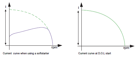
When a three-phase AC induction motor is connected directly to the supply with direct-on-line (DOL) starting, it draws an inrush current of 600–800% of its full-load current (FLA) for the first few seconds of acceleration. On a 90 kW motor with a 160 A FLA, that means 960–1,280 A of inrush current flowing through your cables, switchgear, and transformer for up to 8 seconds. At the same moment, the motor shaft experiences an instantaneous torque application , a mechanical shock through the coupling and into the driven load.
The consequences:
- Voltage dips on the busbar that trip other sensitive equipment
- Thermal stress on motor windings and starter contacts
- Mechanical fatigue on couplings, belts, gearboxes, and pump impellers
- Water hammer in pipework when pumps stop suddenly
- Utility demand charges triggered by high peak current
The Soft Starter Solution: Thyristor Voltage Control
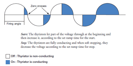
A soft starter solves these problems using thyristors, specifically silicon-controlled rectifiers (SCRs). A typical three-phase soft starter contains three pairs of SCRs, one pair per phase, connected in anti-parallel (one SCR handles the positive half-cycle, the other the negative). This gives full bidirectional control of each phase voltage.
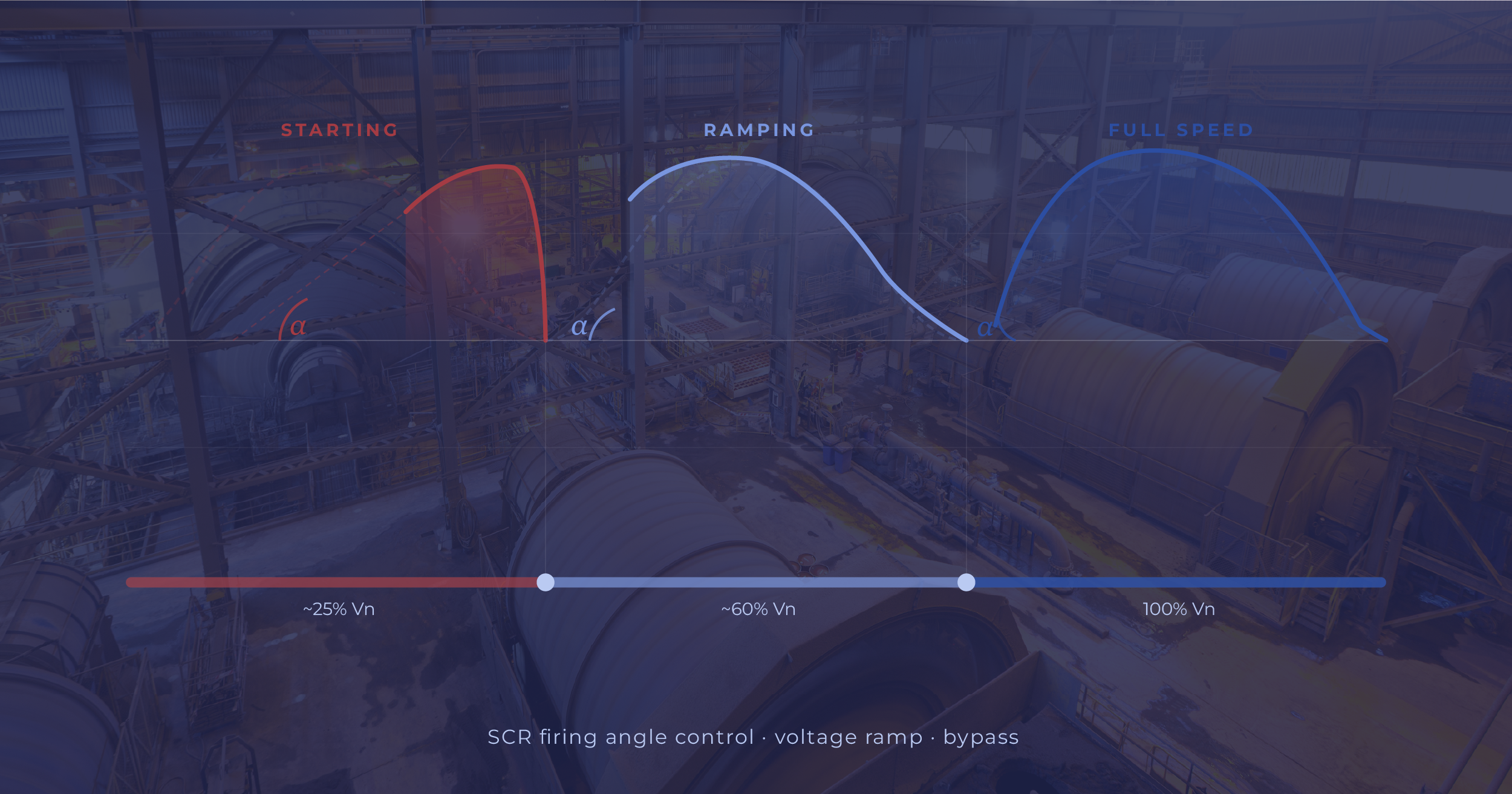
The key property of an SCR is that it only conducts current during the portion of the AC cycle after it is triggered by a gate pulse. By adjusting the timing of this gate pulse, the 'firing angle' (α) — the soft starter controls how much of each half-cycle is delivered to the motor.
The Starting Sequence — Step by Step
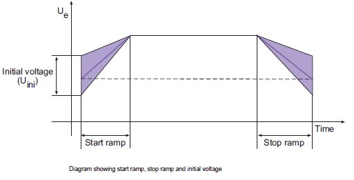
Step 1: Initial Voltage (Pedestal)
At the moment of start, the firing angle is set to a high value (late in the half-cycle), delivering only a small portion of the supply voltage to the motor. This initial voltage is called the 'voltage pedestal' or 'starting voltage' and is typically set between 20–40% of full supply voltage. At this level, the motor begins to develop torque but the current is limited to a user-defined maximum (typically 2–4× FLA rather than 6–8× FLA for DOL).
Step 2: Voltage Ramp
Over the programmed ramp time (typically 5–30 seconds), the firing angle is progressively reduced, meaning the SCRs conduct for a larger and larger portion of each half-cycle. The RMS voltage delivered to the motor rises smoothly from the initial pedestal to full supply voltage. As voltage rises, available torque increases and the motor accelerates the load smoothly, without the mechanical jolt of a DOL or star-delta start.
Step 3: Bypass and Full-Speed Running
When the motor reaches full speed (detected by the current dropping to the running current level), the soft starter activates its bypass. In most modern soft starters, this is an internal bypass contactor that closes to create a direct electrical path around the SCRs, which then stop firing entirely. Some designs use a physical bypass contactor that connects the motor directly across the supply, completely removing the SCRs from the power path.
Either way, the result is the same: the motor runs at full voltage and frequency, with no SCR losses in the steady-state circuit. The soft starter's power consumption during running is negligible.
Step 4: Soft Stop
When the stop command is issued, the soft starter reverses the process. The bypass opens, the SCRs resume control, and the firing angle is progressively increased, reducing the voltage delivered to the motor over the programmed deceleration ramp time. The motor decelerates smoothly, the pump flow reduces gradually, and the check valve closes against near-zero flow — eliminating water hammer entirely.
Current Limiting vs Voltage Ramping
Modern soft starters offer two control modes for starting:
- Voltage ramp mode: The voltage is ramped from the initial pedestal to full voltage over the ramp time. Simple and effective for most applications.
- Current limiting mode: The firing angle is continuously adjusted to keep the motor current at or below a set limit (e.g., 350% FLA). The voltage rises as fast as the load allows without exceeding the current limit. Better for applications with variable load during starting (e.g., loaded conveyors).
- Option 1 – Starting with current limit: Voltage and current rise together until the current reaches the programmed current limit threshold (typically 3–4× FLA). At that point, the voltage holds steady and the SCRs stop advancing the firing angle and remains there until the motor accelerates toward nominal speed and current naturally begins to fall. Only then does the voltage resume its ramp to full supply. This mode gives the tightest control over peak current draw and is the preferred choice for applications where supply capacity is constrained or where other sensitive loads share the busbar.
- Option 2 – Starting without current limit: The current-limit parameter is set to a high value so it is never reached during the start. Current ramps up freely as voltage rises, following the natural torque-speed curve of the motor and load. The soft starter still significantly reduces inrush compared to a direct-on-line start, but acceleration is faster and the starting profile is smoother, making this the better choice for light-duty or unloaded starts where speed of acceleration matters more than peak current control.
What the Soft Starter Cannot Do
A soft starter controls voltage, not frequency. Because the output frequency is always equal to the supply frequency (50 Hz or 60 Hz), the motor can only run at its rated synchronous speed and cannot run at reduced speed under normal operating conditions. If your application requires variable speed, you need a variable frequency drive (VFD). For fixed-speed applications, a soft starter is the more cost-effective and reliable solution.
Soft Starter Motor Protection Functions
Beyond starting and stopping, modern soft starters include a comprehensive suite of motor protection functions that eliminate the need for a separate protection relay:
- Overcurrent protection and electronic overload relay equivalent
- Locked rotor / stall protection (detects motor not accelerating within expected time)
- Phase loss, phase reversal, and phase imbalance protection
- Thermistor input for direct motor winding temperature measurement
- Undercurrent (loss of load) protection — detects pump cavitation or coupling failure
- Overvoltage and undervoltage protection
- Starts-per-hour limiting to prevent thermal cycling damage
This integration makes the soft starter a complete motor management solution rather than simply a soft start device, eliminating a separate protection relay and simplifying the overall control panel design.
Choosing the Right Soft Starter for Your Application
The fundamental sizing parameter for a soft starter is the motor's full-load current (FLA), not its kW rating. Select a soft starter with a rated current at or above the motor FLA. For heavy-duty applications with long acceleration times (crushers, mills, loaded conveyors), select the next frame size up to provide thermal headroom.
Now let's find your product
If you need more help, we're here
Not sure which model fits your application? Use the selector above to get a recommendation in under a minute. Solcon-IGEL manufactures soft starters from 7.5 kW (LV) to 50 MW (MV), covering every industrial application from standard duty pump control to the most demanding offshore compressor starts. Our application engineers are available to review your motor data and confirm the right product — just use the button bellow.